Key results:
1. Flow path visualization and thermal diffusion
2. Flow mixing
3. Internal and external flow modelling
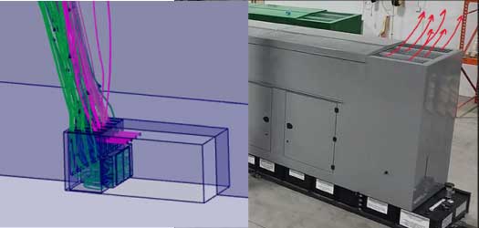
The customer, Abri Concept, noticed that the exhaust gases from the diesel engine of a generator did not dissipate in an adequate way which results in a bad diffusion of gases in the atmosphere.
Therefore, the client wanted to know if adding diffusion blades would help defuse the gases into the surrounding air. In addition, the impact of a secondary flow on the exhaust gases needs to be better understood due to the proximity of both outlets.
Main challenges
1. High-velocity profiles causing convergence difficulties
2. Flow mixing
3. Internal and external flow modelling
To better understand the diffusion and flow path of the exhaust gases, a computational fluid dynamics (CFD) model was created using the FMK role in the 3DEXPÉRIENCE. Geometry from the client’s CAD was used to define this model.
Due to the nature of the flow, steady-state analyses were chosen using both thermal equations and turbulence modelling (SST model).
Results from this analysis were able to demonstrate the improvement of the new position of the flow guides by demonstrating a good mixture of fluids in the environmental air. In addition, while postprocessing the results, some unwanted flow characteristics were seen that were unknown to the client at the time, such as recirculation.
Thus, some recommendations to the original geometry were suggested to improve the design and have a better performing product.
In the end, simulation (CFD) was able to confirm the new design change as well as show existing problematic areas in the system. This was done all without having to build any physical prototype, thus reducing the time-to-market of the product.