Do you work with road load data?
Endurica has been listening to its users and has recently launched a new feature in Endurica EIE. The new feature allows a user to process as many as 6 independent load channels simultaneously. Previously the number of channels was limited to 3.
First, what exactly is Endurica EIE?
Endurica’s proven simulation solutions are the world’s most versatile and best-validated fatigue life simulation system for elastomers. Endurica EIETM (EIE = Efficient Interpolation Engine) rapidly computes full variable amplitude stress-strain histories for a finite element model.
Endurica EIE is a vital tool when looking at road loads or load signals from the field or from multibody dynamics simulations. These applications require more time steps than can be processed efficiently in a direct finite element analysis.
How Does it Work?
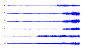
There may be as many as six channels of load input to consider in a fatigue analysis: three moments and three forces. Endurica EIETM software was initially developed to process three independent channels and in early 2022, the capability was expanded to support six channels concurrently.
The user inputs the road load data file (in csv or rpc format) and then EIETM automatically generates a command signal to drive the finite element model boundary conditions along the load space path that will define the interpolation map. The user then executes the finite element model to generate the map.
Finally, EIETM interpolates the data to determine the stress-strain histories, which are used to compute fatigue life.
What else does Endurica EIETM do?
Not only does the software support six independent channels for life predictions, it includes two new utilities: channel reduction and pathfinder.
Channel reduction is used to analyze and reduce map dimensionality.
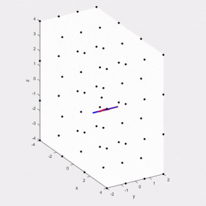
While working with an increasing number of channels, often two or more of the channels are not completely independent from one another. With Endurica EIETM’s channel reduction utility, the number of grid points within one job may be reduced potentially without loss of accuracy (when the channels are highly correlated). This means the software extracts a lower-dimensional representation of the input signal, reducing the computational burdens of map generation and interpolation.
Pathfinder is an auto-generated boundary condition path for map construction.
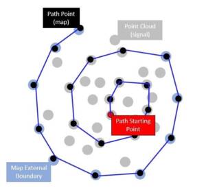
This utility creates a path that begins from the deepest point in the point cloud, then proceeds in an outward spiral in steps of roughly equal size.
Using pathfinder, the software determines the best path within specifications of map size and the number of steps, to analyze the space and to conduct a finite element job.
Pathfinder has been designed to run independently of the channel reduction utility, meaning pathfinder will work within six dimensions if the user wishes. Although the higher dimensions will take longer to work through, the overall computational speed surprises and delights users.
What is the Workflow?
Understanding how each of these features plays into the overall workflow becomes vital knowledge to calculate life prediction. A user starts with six work channels. However, with this number of channels, the user wants to ensure that each variable is truly independent.
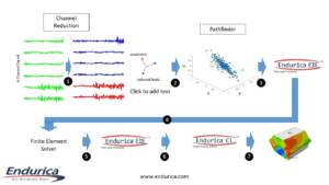
Step 1 includes running the channel reduction procedure, which creates a reduced history and a transform matrix.
Step 2 runs pathfinder, the utility that plans out which precomputed points one needs to successfully build a map with specific data points.
From the path data, a user can conduct Step 3, where the path is transformed back into the original coordinate system.
Finally, the history from the system can be applied in step 4 as a boundary condition for the finite element model to generate strain history for every point on the map.
In step 5, the strain results from the finite element analysis are exported and then associated in EIE with the map.
In step 6, the interpolation process is executed to generate strain/stress history for each finite element.
In Step 7, the fatigue analysis is completed.
Finally, in step 8, the fatigue life predictions are imported to the results database for visualization.
What are my Deliverables?
The data tables below show how fatigue life for two different map sizes (50 points and 100 points) are computed for different degrees of channel reduction. The benchmark life is the no-interpolation data. The leftmost column of the tables represents potential reductions using the channel reduction utility.
The two middle columns of the top data table (Cycles) give life predictions, using different-sized maps. The middle two columns of the lower data table (Ratio) give the accuracy of the predictions compared with the no interpolation benchmark results (i.e. line 3 states 0.95, which means there is a 5% margin of error).
As the map becomes more refined, the results become more reliable across all the different channel reduction levels.
Using the Endurica EIETM process enables the job to finish in under 10 minutes; completing this job without EIE would take around 35 minutes. Additionally, the execution speed advantage of EIETM grows as the road load signal becomes longer.
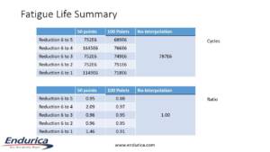
These data tables show how the use of these two new features can benefit a user: high accuracy and low run times.
In Conclusion
- The newly updated Endurica EIETM can support 6 channels, with the accompaniment of two new features: channel reduction and pathfinder.
- The use of the channel reduction feature can help generate higher map accuracy with fewer grid points.
- The use of the pathfinder feature can help automatically generate a finite element solution path that connects all map grid points.
- Interpolated Strains match Strains from the direct computation.
- Computed fatigue life after channel reduction is similar to the original signal, but is significantly faster.

