 In an internal combustion engine, connecting rods play the crucial role of converting the reciprocating motion of the piston into the rotational motion of the crankshaft. Connecting rods undergo severe tension and compression loads due to piston acceleration and deceleration during operation and need to be designed for long life.
Due to the complex nature of the loads, fatigue is the main reason for the failure of these components. Therefore, connecting rods’ fatigue life directly influences engine warranty periods offered by manufacturers.
Imprecise calculation of fatigue life causes significant problems for connecting rods
On one hand, failure of connecting rods before the estimated life causes severe (financial & reputation) implications for manufacturers (recalls, warranty issues).
On the other hand, a too conservative estimate of fatigue life leads to over design and extra costs in material wastage and reduced performance (too heavy).
For those reasons, connecting rods represent good candidates to use as an example to discuss the importance of data sequence loading for better accuracy in fatigue analysis.
A simple way of calculating the fatigue life of connecting rods is to use constant amplitude loading between pure tension and compression. A more detailed way is to use variable amplitude loading captured from tests and use miner’s rule to predict the life. But neither process captures accurately the load history in the component.
The sequence of loads leaves residual stresses behind which play a crucial role in evaluating the component’s life. A simple constant amplitude loading or variable amplitude loading with miner’s summation does not capture these residual stresses.
For example, a small load cycle followed by a stronger damaging load cycle may not cause the same fatigue damage as the opposite sequence (a stronger damaging load followed by a small load). A small load cycle can propagate the damage initiated by a previous large load cycle. Hence, fatigue loading definition with the proper sequence of loads becomes important.
Data sequence loading in FE-SAFE is a powerful feature that allows to accurately predict the life of components considering the sequence of loads. FE-SAFE is a suite of durability and fatigue analysis software and is known for its breakthrough innovation and implementation of advanced features such as multiaxial strain-based algorithms, critical-plane search methods, etc. FE-SAFE can read FEA results from almost all commercial FEA codes and proceed with fatigue analysis. It can also write out fatigue results in the formats understood by commercial postprocessors.
The purpose of this example is to showcase the data sequencing loading in FE-SAFE and a methodology for fatigue analysis of connecting rods.
The Finite Element Modeling of the Connecting Rods
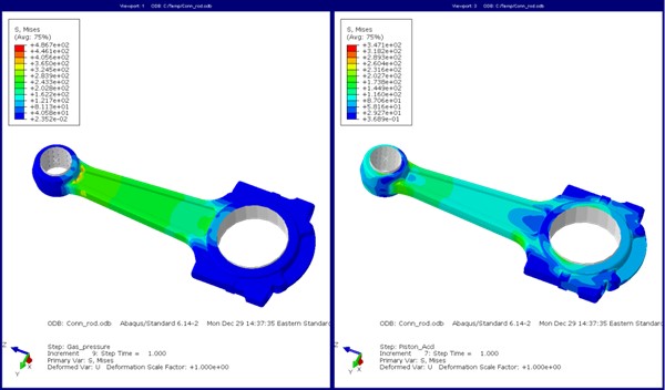
The connecting rod used here is from a heavy-duty diesel engine made of SAE 4140 forged steel. For this case, ABAQUS is used to analyze the structural strength of the rod at all predetermined intervals of crank angle. Gas pressure and piston acceleration loading are used with the corresponding crank angle in a series of non-linear static steps.
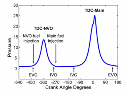
The picture below shows a typical gas pressure variation experienced by the rod at different crank angles for one full cycle of a 4-stroke engine.

In one single ABAQUS non-linear static analysis, 32 steps were created with loads for each step corresponding to 20o crank angle intervals, thereby capturing the complete 720o crank of a 4-stroke engine.
The stress results are generated in one ODB file. Thermal loads are neglected here since the temperature is not really a point of high concern in a connecting rod. The interval between static steps is chosen based on variation in load magnitude and to maintain sufficient accuracy.

Fatigue Analysis of The Connecting Rods

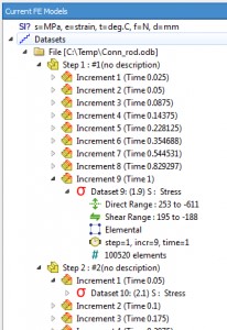
The results of FEA analysis can be easily imported into FE-SAFE. Shown in the figure to the right is a sample of FE-SAFE reading all the increments of a step in an Abaqus ODB file. Converged iterations of Abaqus in an increment are automatically read by FE-SAFE as a dataset. In our problem, we need only the last increment of all the 32 steps; hence we request FE-SAFE to read the last increase of each step.
The loading definition in FE-SAFE becomes a duty cycle with data sequence loading and where stresses for all 32 crank angles are sequenced together to form a complete loading cycle of the 4-stroke engine.
Defining data sequence loading in FE-SAFE is simple and straightforward with just a few clicks. We have 32 datasets, and they are sequenced from 1 to 32 to form a full cycle of loading as shown in the image below. This is the preferred way of defining fatigue loads for such a case of low cycle fatigue scenario having dominant plasticity.

SAE 4140 material is chosen from FE-SAFE database for the strain-life curve. The fatigue results that were requested include FOS (Factor of Strength) for a target life and the actual design life of the component. Please note that FOS in FE-SAFE is not the same as the typical fatigue safety factor.
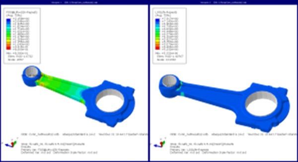
Following are the results obtained for the connecting rod based on the above-mentioned stress, material, and loading conditions.

It can be noted above that the FOS is requested for a target life of 1 million cycles. Lowest FOS reported for the specified target life is around 0.82. The FOS reported here means that the stresses should be scaled down by a factor of 0.82 to achieve the target life. FE-SAFE reports actual life of the component in log-log scale for better visualization. The lowest value reads 5.232 on log scale which equals to 170000 cycles. This zone with 170000 cycles can be assumed to be the potential crack initiation zone.
The Power of Doing Fatigue Analyses With FE-SAFE
Data sequence loading is a powerful feature in FE-SAFE. While it may not always be feasible to follow this methodology for small design changes in the product development process due to the detailed FEA and fatigue simulations required, the methodology should nevertheless be followed as a final check before freezing the design.
The methodology for fatigue of connecting rods is a realistic representation of physical phenomena wherein the loading history is considered in calculating the life of the component. The methodology utilizes powerful and matured FEA technology and can be really accurate in predicting the fatigue life of the connecting rod.
FE-SAFE comes with a large database of materials with fatigue properties (stress-life and strain-life curves) required for fatigue analysis. One of the most distinguishing features of FE-SAFE is the availability of modern multiaxial strain-based algorithms. Taking elastic stresses from FEA, FE-SAFE uses multiaxial plasticity corrections to evaluate strains and employ multiaxial strain-based algorithms such as Principal strain, Brown-Miller, etc. with mean stress corrections such as Morrow, SWT etc. to accurately predict the life of the component.
It is these strain-based algorithms that enable FE-SAFE to be used confidently in low cycle fatigue scenarios, where plasticity is dominant. In a typical fatigue analysis using hand calculations, engineers make a lot of assumptions such as constant amplitude loading, uniaxial conditions, no plasticity corrections, etc.
On the contrary, FE-SAFE offers advanced multiaxial algorithms, multiaxial plasticity corrections, complex loading conditions, etc. in an ease-to-use environment, thereby enabling engineers to evaluate fatigue behavior more realistically.
Hyundai Motor Company has presented a research paper on this topic for an automotive knuckle. They highlighted the importance of load sequence in presence of overload, by comparing experimental test results to FE-SAFE prediction.
References
1. The Effects of Overload on the Fatigue Life, Hyundai Motor Company, SIMULIA Community Conference 2010
2. Abaqus Documentation, Dassault Systemes SIMULIA
3. FE-SAFE documentation, Safe Technology, Dassault Systemes

