Piping is very common in oil and gas industry especially in oil refineries. Petroleum refineries run as efficiently as possible to reduce costs. One major factor that decreases efficiency is corrosion of the metallic components found throughout refining process especially in pipes with wall thinning phenomena. Corrosion causes the failure of equipment items as well as dictating the maintenance schedule of the refinery, during which part or the entire refinery must be shut down. A study showed that corrosion-related direct cost in the U.S. petroleum industry as of 1998 was estimated at US$3.7 billion per year. In addition, this is becoming worse when there are tragedy strikes eg.October 2011 explosion at CCRL crude oil refinery in Regina in the province of Saskatchewan in Canada resulting from a pipe corrosion leading to 52 people injured and damage estimated at $100 million. Let alone the downtime post disaster.
Modern NDT and X-ray scanning techniques have enabled engineers to identify corrosion defects at early stages and make decisions on preventive measures but it should also be noted that these corrosion defects even on a minor scale can cause significant reduction in design burst pressure. This blog aims at using the advanced finite element technology to capture wall thinning on pipes from NDT scanning techniques and re-evaluate the new burst pressure based on existing corrosion-related defects. Abaqus unified FEA product suite from Dassault Systemes brand SIMULIA’s portfolio is utilized to demonstrate this capability.
Wall Thinning
Wall thinning due to corrosion can be captured by scanning the section of the pipe of interest. The scanned data can be processed to get output in cylindrical coordinates in excel with reduction in radius against circumference (θ) and axial direction (Z) as shown in a flat pattern below

Finite Element Model
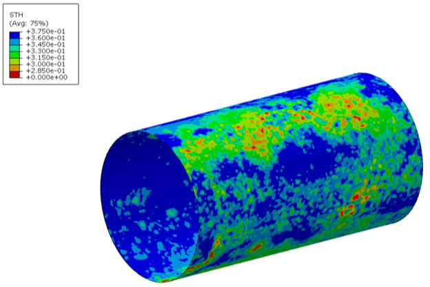
A simple shell model of the pipe with the inner radius can be constructed in Abaqus/CAE and meshed using shell elements. To define the wall thinning due to corrosion, nodal thickness definition can be employed using mapped fields. Shown below is the thickness variation due to corrosion on the pipe within Abaqus/CAE.

ASME B31 – Code for Pressure Piping
ASME B31 is widely used code in the industry for pressure piping and it can be used to calculate Maximum Allowable Operating Pressure (MAOP) for pipes. As per the code, we could calculate the MAOP for unflawed pipe using the formulation below for typical material ASTM A106B used in piping industry with yield strength of 35000Psi.

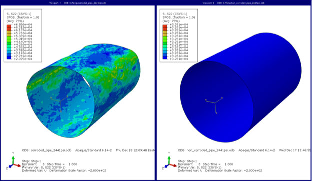
Based on the formulation, the calculated MAOP for a non-corroded pipe is 2441Psi. Applying this pressure to both corroded (left) and non-corroded pipes (right) on the FEA model yields results as shown below.

The figure shows deformation patterns and amplified deformation under the MAOP pressure loading and it is clear that radial deformation is not uniform once corrosion takes place. It can also be clearly noted that MAOP as per ASME B31G does not hold good for corroded pipes with stresses exceeding the yield limit of 35000Psi.
Therefore it is evident that a flaw due to corrosion can severely degrade performance of the pipe and MAOP has to be recalculated to find the new safe operating pressure with defects.
Safe Operating Pressure
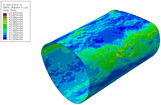
Finite element technology offers the flexibility of back calculate the safe operating pressure on a corroded pipe and by employing this we are able to find the new safe operating pressure to be around 1200Psi. Corresponding hoop stress is less than yield and is shown below. This could be the new burst pressure of the pipe having corrosion.

ASME B31 code offers ways to recalculate a safe operating pressure based on existing flaws from corrosion. The formula is based on largest depth of the flaw in the pipe as shown here.

Based on this equation, newly calculated safe operating pressure is found to be around 916Psi. It has to be noted here that this is usually more conservative than FEA based evaluation since the size of defect can be taken as quite large in the case of corrosion. Not easy to define accurately.
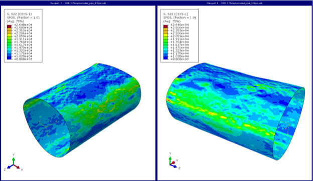
Applying the conservative safe operating pressure from ASME B31 code to the FEA model shows results as below.

It may be noted that the hoop stress is well below yield limit and is found to be around 75% of yield.
Conclusion
The key objective of this study was to develop a quick and accurate process using ABAQUS finite element modelling to represent detailed corrosion in a pipe and evaluate applicable MAOP. This new burst pressure from FEA was checked against the conservative safe operating pressure from ASME B31G and was found to be reasonably good estimate, but is more accurate. This methodology can be very well extended for advanced fracture mechanics studies for FFS assessments based on API 579-1 FFS code.
Scope of Future Blog
With a simple script on python this finite element model reverse engineered from NDT scans can be converted into a 3D model with hexahedral elements. The 3D model can be further used to conducting intensive fracture mechanics studies to evaluate Stress Intensity Factor (SIF), J-integral, etc., for FFS (Fitness for Safety) assessments as per API 579-1 FFS code. Abaqus offers a variety of crack propagation models to assess the pipe as per API standards as follows
- LEFM – Linear Elastic Fracture Mechanics.
- EPFM – Elastic Plastic Fracture Mechanics
- XFEM – Extended Finite Element Method
References:
- ASME B31.3 – 2012 code for pressure piping, The American Society of Mechanical Engineers
- Abaqus 6.14 Documentation, Dassault Systemes SIMULIA
- API 579-1/ASME FFS-1, JUNE 5, 2007, The American Petroleum Institute
1 Comment
Dillon
Truly when someone doesn’t know after that its up to other visitors that they will assist, so here it takes
place.