

The Challenge
Low Earth orbit is getting crowded, and a growing number of satellites now carry optical sensors whose job is to watch it. These space situational awareness (SSA) missions detect and track other objects in orbit to support collision avoidance and safer space traffic management — and they can only do that job as well as their optics let them see. In this field, performance is not only about the light an instrument is designed to capture; it is just as much about the light it needs to keep out.
That was the starting point for this project. A satellite operator came to Optimec (now part of TECHNIA) with an on-orbit optical instrument that was returning more background noise on its detector than expected. Left unaddressed, that noise threatened to erode the sensitivity the mission depended on. The operator needed to understand where the unwanted signal was coming from — and, just as importantly, what could realistically be done about it.
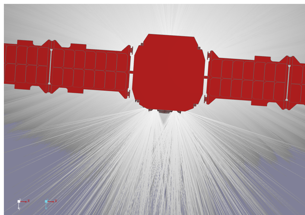
Answering that question meant reconstructing, in detail, the optical environment the spacecraft actually flies through: sunlight reflected off the Earth, glancing light from openings in the structure, and a handful of harder-to-pin-down secondary effects. That is a radiometric problem, not a purely thermal one, and it called for a tool built specifically for it. The Airbus Systema suite is best known as a comprehensive thermal-analysis platform for space systems, but its ray-tracing engine — built to compute radiative coupling and orbital power for complex geometry in the space environment — was the real enabler here. A full thermal model was not required; what mattered was Systema’s ability to trace light paths through a detailed geometric model, and its Python API, which made it possible to automate that process into repeatable sensitivity studies rather than one-off runs.
Objective and Scope
The objective was to characterize the in-orbit optical environment of the telescope, explain the unwanted absorbed power showing up on its detector by building a correlated digital twin in Systema, and then use that understanding to improve the optical design using Dassault Systèmes’ 3DEXPERIENCE platform.
In practice, that meant working through the following scope:
-
- Defining the boundary conditions relevant to a space-based optical analysis — Earth albedo, lunar flux, solar power, limb effects, glint angle, and related considerations.
-
- Building Earth albedo maps aligned with the mission’s actual geometry and the season being analyzed.
-
- Creating a virtual twin of the spacecraft and its payload.
-
- Correlating simulation results against flight data to identify the main contributors to stray light.
-
- Proposing and validating a design enhancement to reduce detector noise
Our Approach
-
- Model correlation — build and validate the Systema model, apply the mission’s boundary conditions, tune optical properties, and investigate signal peaks and environmental effects (Earth albedo, limb, Moon, solar glint).
-
- Root-cause synthesis — rank the contributors to unwanted flux (e.g. Earth albedo, surface condition, baffle gaps, glint paths).
-
- Design optimization — explore baffle concepts, first against optical objectives and then structural constraints, and validate performance with both contaminated and clean optics.
-
- Conclusions and recommendations — summarize how much improvement was achieved and what the Systema / 3DEXPERIENCE workflow adds to this kind of study.
Where the Model Reaches Its Limits
No model is the mission, and it is worth being upfront about where this one simplifies reality. Optical properties were defined at a single wavelength (index of refraction, absorptivity/emissivity, specular and diffuse reflection, and so on). Systema also works from a constant solar flux, so absorbed power from the simulation was scaled to match the detector’s operational range rather than modeled as a time-varying input. Finally, a few effects — limb brightening, low-level lunar flux, and galactic background — could not be fully represented within the tool or the mission data available, and are called out explicitly where they matter below.
Building a Digital Twin
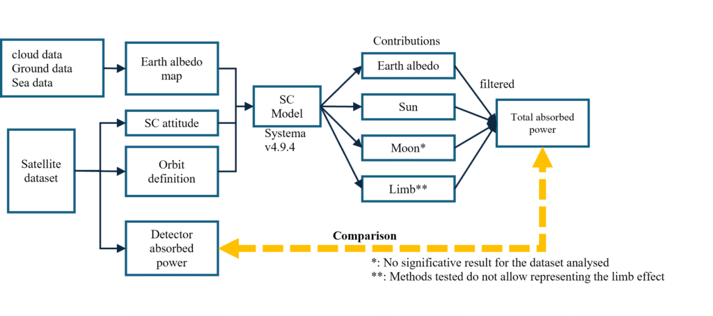
Workflow Overview
Model Creation
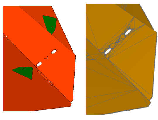
The model was built in two parts. Optical surfaces were constructed from geometric primitives — cylinders, plates, spheres — to preserve an accurate surface representation where it mattered most for ray tracing. The surrounding spacecraft environment, meanwhile, was imported directly as tessellated CAD geometry, using Systema’s built-in support for that format.
Model Validation
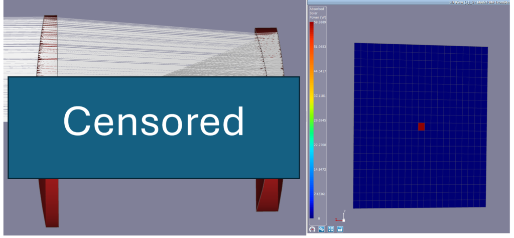
Before trusting the model with real boundary conditions, the optical path itself needed checking. Ray tracing was run from source to detector on a representative telescope configuration to confirm that light was travelling where it should — and being blocked where it shouldn’t.
Setting the Boundary Conditions
With the geometric model in place, attention turned to the environment around it:
-
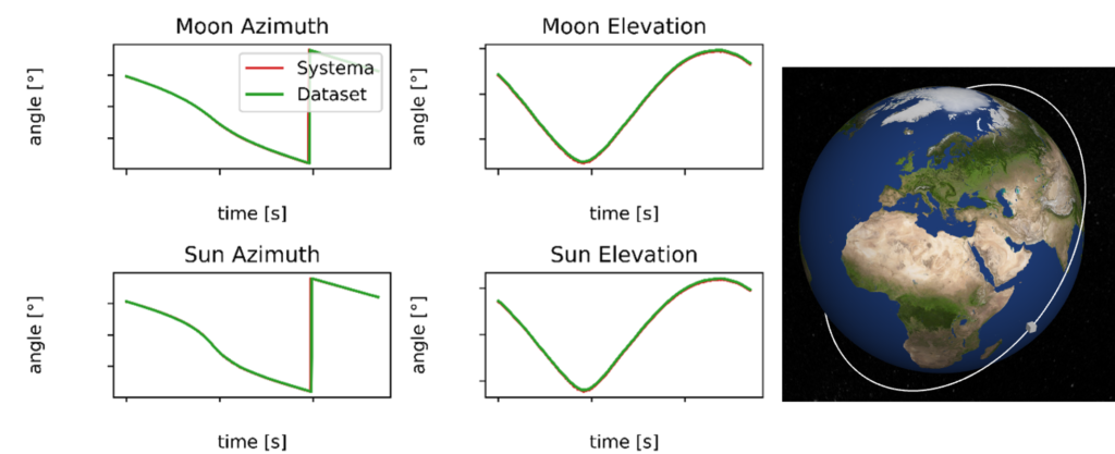
- Trajectory and attitude — taken from the operator’s own flight datasets, which lined up well with Systema’s outputs.
-
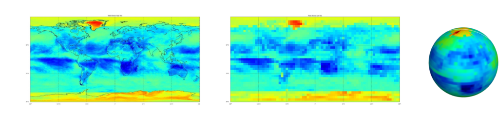
- Earth albedo mapping — built from maps combining land, sea, and cloud albedo across the seasons, so the model could reflect how the view of Earth changes through the year.
-
- Limb effect — investigated separately (see below).
-
- Moon effect — investigated separately (see below).
-
- lar glint angle — investigated separately (see below).
Correlating with Flight Data
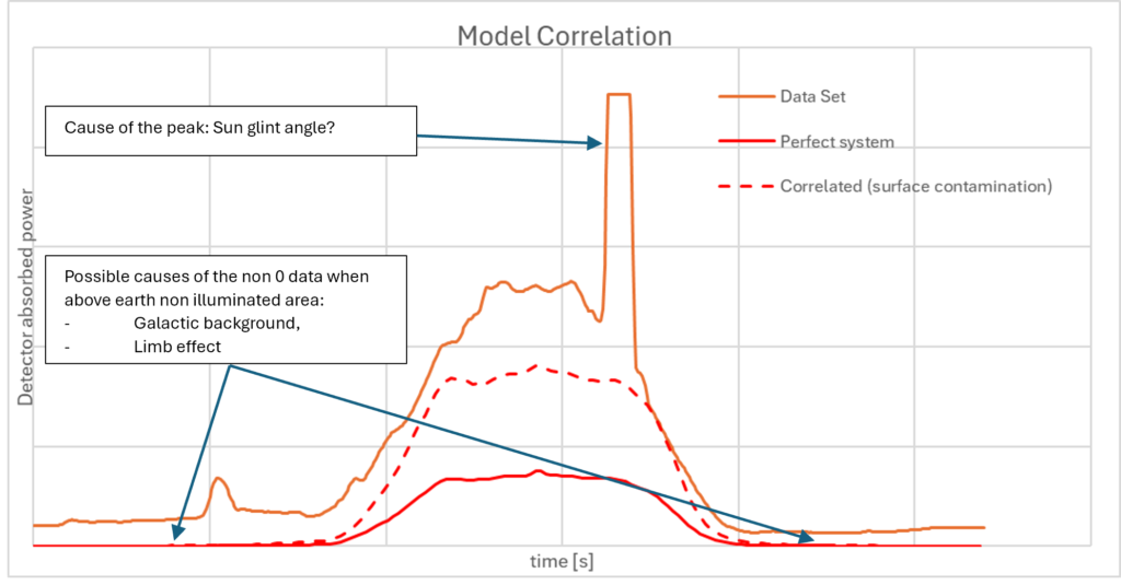
Several flight datasets were used, each corresponding to a different spacecraft attitude. In the first, the spacecraft had a substantial view of the Earth; in the others, it was looking farther away, reducing the albedo contribution and bringing secondary effects — atmospheric limb, galactic background, lunar albedo — further into the picture.
Optical properties were fine-tuned surface by surface to match the flight datasets, with adjustments concentrated on the areas where degradation was plausible — scratches in paint, contamination on optics. Including these surface imperfections brought the simulation noticeably closer to the flight data. Galactic background, which was not modeled, may explain a small constant offset that remained. Overall correlation was solid, but three questions stayed open: what was causing the high peaks in the dataset, whether the Moon could be represented when present, and whether the limb effect could be captured at all. At this stage, the team attributed the non-zero signal observed above Earth’s non-illuminated areas to galactic background and/or limb effects, and hypothesized that the peaks were related to solar glint
Limb Effect
The atmospheric limb effect — sunlight scattered in the atmosphere before it reaches the ground — produces a bright halo around the Earth’s edge. Systema has no native model for this. Two workarounds were tried: a diffuse, semi-transparent cone approximating the halo, and an adjustment to spacecraft altitude using a dataset chosen because albedo should have played a secondary role there. Neither approach reproduced the flight data convincingly, and the limb effect remains one of this study’s open questions.
Glint Angle
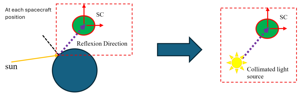
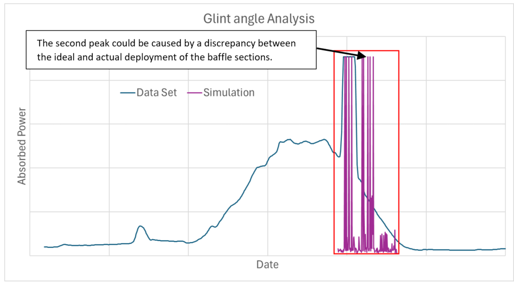
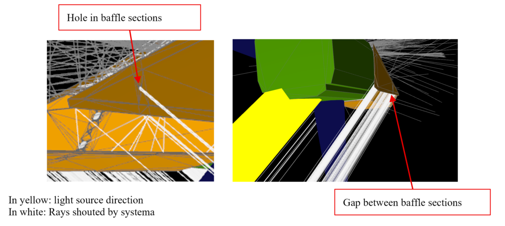
The high peaks turned out to trace back to solar glint (specular reflection of the sun to the Earth) finding its way through openings in the spacecraft’s deployable baffle. Systema does not model solar glint directly, so local light sources were used to reproduce the effect qualitatively, with an arbitrary power level and a partial-orbit analysis chosen to keep computation time manageable. The simulation showed that glint combined with the baffle openings was consistent with the observed peaks. An additional peak is observed in the simulation but not in the dataset which may reflect a discrepancy between the ideal and actual deployment of the baffle sections.
Moon Effect
Systema can include multiple celestial bodies in its flux computations, but adding the Moon did not match expectations for this particular dataset. The most likely explanation is that the signal involved was extremely faint — low enough that the model may simply not have had the precision to resolve it reliably.
Connecting the Dots
Bringing the correlation work and these targeted investigations together made it possible to rank what actually drives unwanted power on the detector.
Primary contributor (baseline operations): Earth albedo dominates absorbed power during typical mission attitudes. Matching flight levels required both the seasonal albedo maps (land, sea, cloud) and surface optical properties that accounted for contamination.
Peaks and transients: The sharpest spikes were best explained by solar glint — specular reflection off the Earth — combined with openings in the deployable baffle. Once both were represented together in the model, simulated peaks lined up with flight data.
Secondary and unresolved effects: The non-zero signal seen above Earth’s night side may include galactic background (not modeled, and a possible source of a constant offset) and limb scattering (workarounds tested, but not validated). Lunar flux, at very faint levels, could not be confirmed within Systema’s precision for this geometry.
Implications for design: Mitigation needed to target stray-light paths through baffle gaps and deployment tolerances, robustness to contaminated optics, and a geometry that limits glint. These three priorities shaped the design-optimization phase that followed.
From Diagnosis to Design
The correlation work pointed squarely at the main sources of noise on the detector: surface contamination, degradation of the paint finish, the spacecraft’s Earth-facing attitude during normal operations (and the albedo that comes with it), and gaps in the optical system left by the baffle’s deployment mechanism.
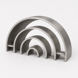
With those levers identified, the design work focused on two things: closing off unnecessary aperture paths on the existing baffle, and sizing a secondary baffle that would improve optical performance without compromising the mechanical loads the assembly needs to withstand. That secondary baffle takes the form of partial concentric cylindrical sections connected by structural arms. The optimization itself proceeded in three phases:
Optical phase — reduce stray light, exploring cylinder thickness and diameter under the assumption of contaminated optical surfaces.
Structural phase — minimize the shadow the new baffle casts on the entrance aperture, while keeping the assembly’s stiffness well clear of the frequencies it needs to avoid, by adjusting anchoring location, link position, height, and thickness.
Validation phase — re-run the analysis with both contaminated and clean optics to confirm the design held up under either condition.
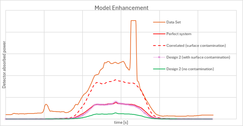
The optimized configuration reached performance comparable to the uncontaminated baseline, even while the optics in the analysis remained contaminated — with further gains still available if contamination can be reduced operationally.
Outcome
This study correlated an optical model against the as-operated system using Systema, and in doing so clarified the main drivers behind unexpected on-orbit measurements — Earth albedo, solar glint, and baffle geometry chief among them. Some phenomena, like limb and Moon effects, remain partially open due to modeling and tool limitations. Even so, the understanding gained was more than enough to give the client a clear path from diagnosis to mitigation.
A revised baffle concept, developed together with 3DEXPERIENCE and Systema, delivers a meaningful reduction in stray-light noise while maintaining strong performance even when optical surfaces remain contaminated.
This project marked our first application of Systema to an optical stray-light problem, and it has since grown into an ongoing collaboration: we are now applying the same digital-twin approach to additional configurations and operating conditions for this program — deepening both our expertise with the tool and the value we can bring to future clients facing similar optical-performance challenges in orbit